Introduction
The performance optimization and cost control of optical systems rely on the precise control of production specifications, surface specifications, and material specifications. Based on ISO international standards and industry practices, this article systematically analyzes the three core parameter systems of optical components, covering the definition, classification standards, and actual impact of 15 key indicators. Through data table comparison, international specification citation, and case analysis, it provides feasible solutions for optical design, manufacturing, and procurement, helping enterprises balance performance and cost and improve market competitiveness.
Production Specifications: The Cornerstone of Mechanical Adaptation and Optical Path Stability
Production specifications directly affect the mechanical compatibility and optical path accuracy of optical components, and a dynamic balance must be achieved between manufacturing feasibility, cost, and performance.
1. Diameter Tolerance: The First Line of Defense for Installation Accuracy

The diameter tolerance defines the allowable deviation range of the outer diameter of the optical component, which directly affects the alignment accuracy of the mechanical axis and the optical axis. If the tolerance is too large, the optical axis may shift by more than 0.5°, causing imaging distortion. The tolerance standards for different precision levels are as follows:
| Quality Level | Tolerance Range (mm) | Typical Application Scenarios |
|---|---|---|
| General | +0.00/-0.10 | Consumer lenses, lighting systems |
| Precision | +0.00/-0.05 | Microscope objective lens, camera module |
| High Quality | +0.000/-0.010 | Laser collimator, astronomical telescope |
Case: A lens with a diameter deviation of more than 0.1 mm may cause a 50 μm shift in the spot during installation, affecting the laser cutting accuracy.
2. Center Thickness and Curvature Radius: Dual Scale for Optical Path Design
- Center Thickness Tolerance: For every 0.1 mm increase in deviation, spherical aberration increases by 15% :
| Quality Level | Tolerance Range (mm) |
|---|---|
| General | ±0.20 |
| Precision | ±0.050 |
| High Precision | ±0.010 |
- Curvature Radius Tolerance: High-precision lenses must be controlled within ±0.01%, otherwise the focal length deviation can reach 1%. For example, if the error of a lens with a curvature radius of 100 mm is ±0.1 mm, the focal length changes by 0.3 mm.
3. Chamfer and Clear Aperture: Co-Design of Protection and Efficiency
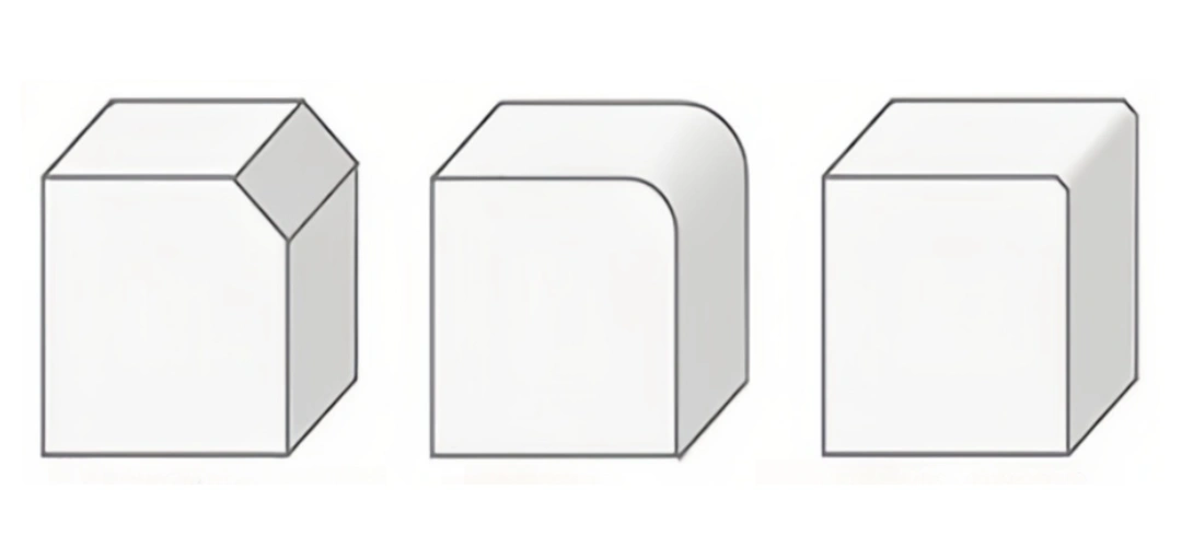
Chamfer can prevent edge damage, and its width needs to be controlled according to the diameter classification :
| Diameter Range (mm) | Maximum Chamfer Width (mm) | Applicable Scenarios |
|---|---|---|
| 3.00–5.00 | 0.1 | Microlens array |
| 5.01–25.4 | 0.25 | Camera lens |
The clear aperture needs to ensure an effective area of more than 90% of the diameter to avoid edge defects from scattering light energy:
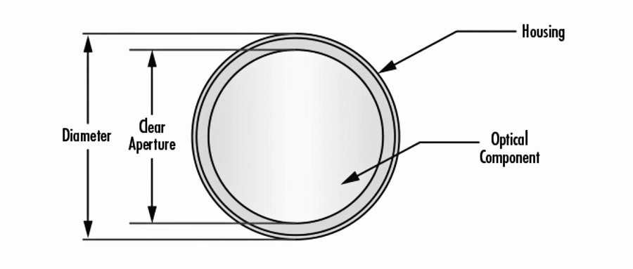
| Diameter (mm) | Clear Aperture Requirements |
|---|---|
| 3.00–10.00 | ≥90% diameter |
| ≥50.01 | Diameter–1.5mm |
Surface Specifications: The Transmission Chain from Microscopic Defects to System Performance
Surface quality directly determines the light scattering, absorption efficiency, and laser damage threshold, and is the watershed of high-end optical systems.
1. Surface Quality: Quantitative Grading of Scratches and Pits
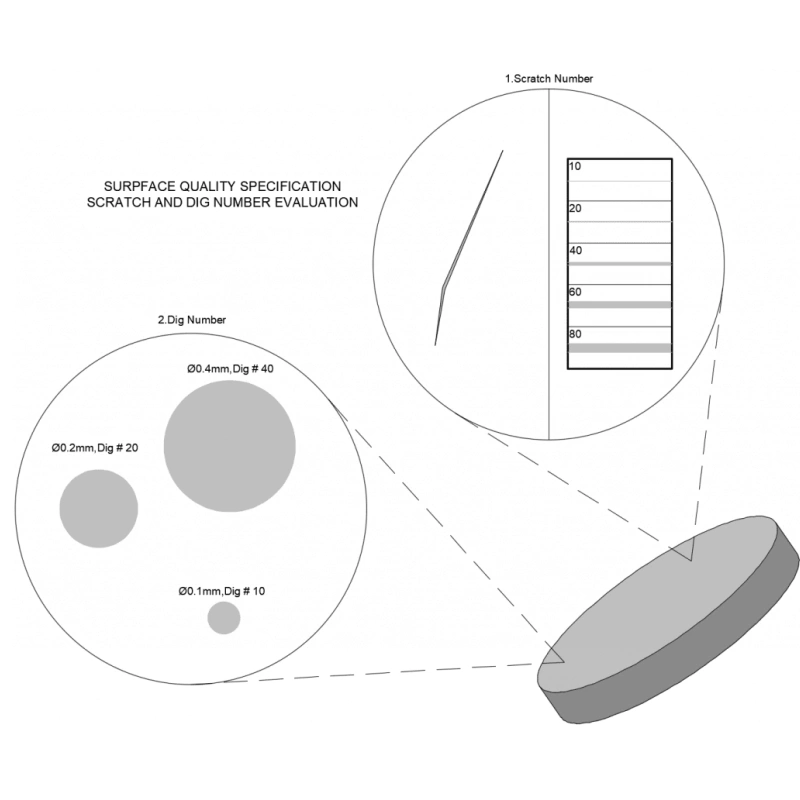
According to the MIL-PRF-13830B standard, surface defects are graded by scratch-dig :
| Grade | Scratch Width (μm) | Pit Diameter (μm) | Applicable Scenarios |
|---|---|---|---|
| 80-50 | ≤80 | ≤500 | Industrial lighting |
| 60-40 | ≤60 | ≤400 | Medical endoscope |
| 20-10 | ≤20 | ≤100 | High-power laser reflector |
Experimental Data: In high-power laser systems, the risk of damage to optical components with scratches exceeding the 60-40 grade increases by 3 times.
2. Flatness and Aperture Number: The Precision Code of Interferometry
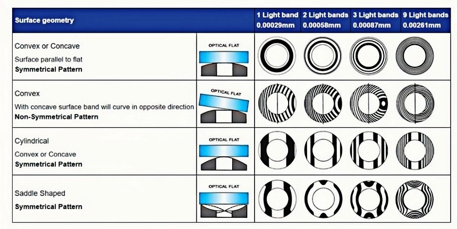
- Flatness: Measured in wavelength (λ), detected by optical flat crystal. High-precision flatness needs to reach λ/20 (≈31.65 nm), and each fringe corresponds to ½λ deviation.
- Aperture Number: The number of Newton rings reflects the curvature deviation. For example, 5 Newton rings represent a surface deviation of 2.5λ, resulting in a lens wavefront error of more than λ/4.
3. Surface Roughness: The “Invisible Killer” of Laser Systems
Excessive roughness (>50Å RMS) will cause the laser damage threshold to decrease. UV laser systems require a roughness of ≤5Å RMS to avoid catastrophic failure caused by microcracks (Figure 4).
Material Specifications: The Physical Nature of Optical Performance
Material properties determine the refraction, dispersion, and durability of optical components, which is the underlying logic of system design.
1. Refractive Index and Inhomogeneity: The Cornerstone of Optical Path Design
- Refractive Index Range: N-BK7 (1.517) to Germanium (4.003), infrared materials require special design.
- Inhomogeneity Level: High uniformity glass (level 5) can reduce wavefront distortion to less than λ/10 :
| Level | Refractive Index Change (×10⁻⁶) |
|---|---|
| 0 | ±50 |
| 5 | ±0.5 |
2. Chromatic Dispersion Coefficient: The Key to Aberration Control
The difference in dispersion between crown glass (Vd>55) and flint glass (Vd<50) can be used in achromatic design. For example, the combination of N-BK7 (Vd=64.2) and F2 (Vd=36.4) can eliminate the secondary spectrum.
3. Laser Damage Threshold: The Life and Death Line of High-Energy Applications
The threshold depends on the pulse type (e.g., Ti:Sapphire mirror: 0.5 J/cm² @150 fs). Reducing the energy density below the threshold by beam expansion can extend the component life.
Summary
The scientific definition of optical parameters is the core of balancing performance, cost, and manufacturing feasibility. Production specifications ensure mechanical adaptability, surface specifications determine optical efficiency, and material specifications lay the physical foundation. By following ISO standards, citing authoritative guidelines (such as Edmund Optics), and making data-driven decisions, companies can optimize optical system design and improve market competitiveness.